



ENG
HOMEConnector InformationHow to Use Pin Header?

  • How to Use Pin Header?

  • 2026-10-14

Before pin header connectors became a standard feature of printed circuit board design, electrical equipment was commonly assembled through point-to-point wiring, soldered terminals, screw connections, wire-wrap posts, and other labor-intensive methods that permanently joined individual components. These techniques were workable for early technologies, but they became increasingly impractical as electronic systems evolved and required denser circuit layouts. Thankfully, the development of the printed circuit board replaced much of the loose wiring with conductive copper traces. However, PCBs still needed a practical way to connect with other circuit boards, ribbon cables, programming equipment, sensors, switches, power supplies, and removable electronic modules. 
Enter electronic connectors: technology enabling power, signal, and data circuits to be joined without permanently bonding every part of the system. Pin headers emerged as one of the simplest forms of this technology: rows of conductive pins held at a controlled spacing by an insulating housing and mounted directly onto a PCB. Their standardized geometry made it possible to connect daughtercards, jumper wires, female sockets, cable assemblies, development tools, and test fixtures without creating a separate soldered wire for each circuit. Pin header connectors transformed individual PCB circuits into accessible, modular, serviceable, and repeatable connection points.

How Does a Pin Header Work?

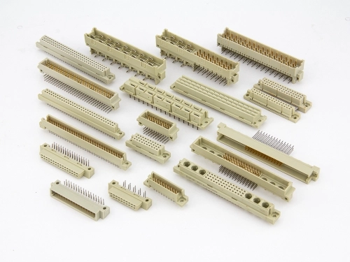
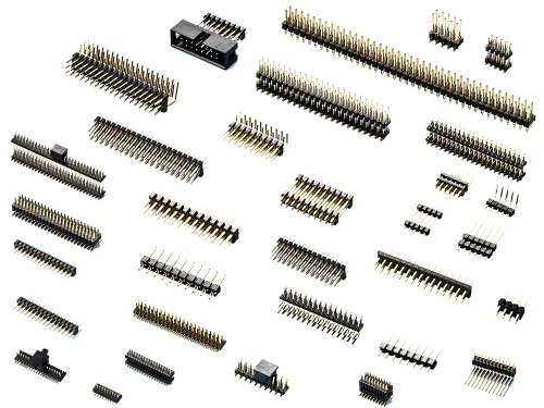
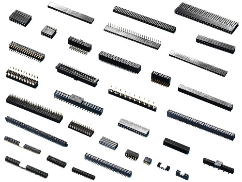
Pin header connectors are male, and only male, but female counterparts are typically called sockets or receptacles. Pin headers come in various position counts and pitches, including common 2.54 mm, 2.00 mm, and 1.27 mm centerlines, with copper-alloy pins providing conductivity and thermoplastic housings providing insulation. Their contacts may be plated with tin, gold, or selective combinations to balance solderability, durability, and cost.
A pin header creates a separable electrical path between the PCB and a mating female contact. One end of each male pin is mechanically and electrically attached to a plated through-hole, surface-mount pad, or press-fit hole on the PCB, connecting the pin to a copper trace within the circuit board. The exposed mating end will then enter a spring contact inside the female socket. As the two halves engage, the receptacle applies force against the pin, producing a stable metal-to-metal contact interface. A small sliding movement, known as a contact wipe, can help displace light surface films and establish a consistently dependable conductive path. 
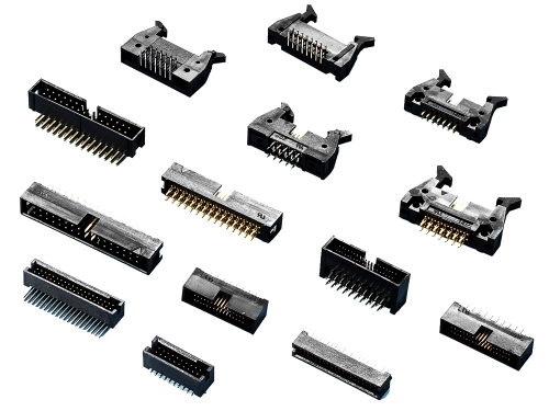
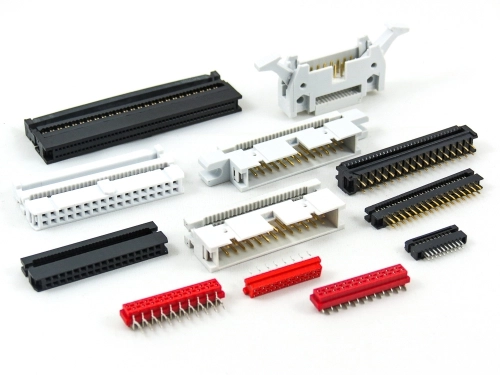
Once mated, individual positions may carry ground, low-voltage power, analog signals, digital logic, clock lines, programming signals, control commands, or serial data, depending on the PCB’s pin assignment. Pin headers do not decide what information travels through them; they provide the physical interconnect architecture through which the circuit operates. A header may connect one PCB directly to another in a board-to-board or mezzanine arrangement, connect a PCB to individual wires through a crimp housing, or connect a board to a ribbon cable through an insulation-displacement connector. Shrouds, polarization features, keys, alignment posts, latches, guide pins, and ejector levers may be added to reduce mismating, protect the pins, improve retention, and/or simplify cable removal.

Using a Pin Header Correctly

To use a pin header correctly, begin by defining the electrical, mechanical, environmental, and manufacturing requirements instead of selecting a connector by appearance alone. Determine the number of circuits, row count, pitch, orientation, board spacing, pin length, current per contact, voltage, signal frequency, operating temperature, mating-cycle requirement, and available PCB area. Verify the header and female receptacle have compatible pitch, contact dimensions, plating, pin count, keying, and insertion depth. 
Once those steps are satisfied, select the termination style: through-hole pin headers place their tails into drilled PCB holes and are soldered on the opposite side, providing useful mechanical anchoring; surface-mount headers are soldered directly onto pads and support automated pick-and-place assembly, smaller products, and layouts where drilled holes are undesirable; and press-fit contacts are inserted into correctly dimensioned plated holes, creating a solderless mechanical and electrical connection through a solid or compliant press-in zone. 
During PCB assembly, keep the header square to the board, protect the contacts from bending, follow the recommended footprint, and use the manufacturer’s soldering profile and processing instructions. After assembly, inspect solder joints, alignment, coplanarity, contamination, and pin damage. Mate the connector straight rather than rocking it from side to side, and never use a header as a mechanical handle for the PCB. Current ratings must also be interpreted carefully. 
A published current-per-contact value can depend on ambient temperature, PCB copper, wire size, contact spacing, and the number of simultaneously energized contacts because neighboring circuits heat one another. Connector current-carrying-capacity testing therefore evaluates temperature rise under different loading arrangements rather than treating every pin as thermally isolated. For high-speed signals, engineers must additionally examine impedance discontinuities, crosstalk, return-path placement, pin-field assignments, and unmated pin length, since a connector performing well for low-frequency control signals may not be suitable for a multi-gigabit interface.

What Industries Use Pin Headers?

Pin headers allow manufacturers to build subsystems separately and connect them during final assembly. Thankfully, developers, understanding its simply construction, can replace modules without redesigning the entire PCB, supporting low-volume prototypes and automated mass production. Breakaway terminal strips can also be divided into smaller position counts, while standardized socket interfaces allow one controller or motherboard to accept multiple compatible modules. Additionally, vertical headers conserve horizontal board space, right-angle headers provide access along a PCB edge, and elevated or stacking headers establish controlled distances between parallel boards. Finally, fine-pitch products increase interconnect density, while shrouded or locking designs improve protection and mating security. Pin headers, therefore, are not limited to a single market. These male connectors appear wherever designers need a compact PCB component supporting power, signal, data, configuration, diagnostics, or modular board-to-board connectivity. You can find pin headers in nearly every major industry, including: 

  • Consumer Electronics
  • Computers and Computer Peripherals
  • Embedded Systems
  • Telecommunications
  • Data Centers
  • Cloud Computing
  • Industrial Automation
  • Robotics
  • Automotive Electronics
  • Commercial Vehicles
  • Aerospace
  • Space Systems
  • Defense Electronics
  • Medical Electronics
  • Test and Measurement
  • Semiconductor Manufacturing
  • Energy and Power Systems
  • Electric-Vehicle Infrastructure
  • Transportation
  • Appliances
  • Building Automation
  • Security and Surveillance
  • Internet of Things
  • Agricultural Technology
  • Laboratory and Scientific Research
  • Education and Training
  • Broadcasting and Professional Media
  • Retail and Point-of-Sale Systems
  • Entertainment Technology
  • Contract Electronics Manufacturing

Where to Find Affordable Pin Headers?

Finding an affordable pin header requires more research than locating the lowest unit price. Connector selection can affect PCB layout, assembly efficiency, field reliability, repairability, and the long-term availability of replacement parts. Before choosing a connector, compare specifications such as pitch, dimensions, PCB footprint, plating, contact resistance, current and voltage ratings, temperature range, mating cycles, packaging, and compatibility with the recommended mating connector. Engineers should also evaluate polarization, pin protection, board retention, coplanarity, flammability ratings, regulatory compliance, and product lifecycle to ensure the connector meets both manufacturing and application requirements. A lower-priced connector may ultimately cost more if it creates assembly problems, requires additional labor or tooling, causes failures, or forces future PCB redesigns.
Connector manufacturers should be researched for the breadth of their pin-header portfolio, documentation quality, manufacturing consistency, available mating components, engineering support, order quantities, lead times, and distribution network. Fortunately, engineers and buyers comparing affordable electronic connectors can review Oupiin Enterprise’s available series options, examine the relevant product specifications, and contact the company to discuss pitch, mounting style, orientation, pin count, plating, packaging, and application requirements. Contact us today!


202502211359388tpM   20250221140032bqsM   20250221140042bUxX